| |
     |
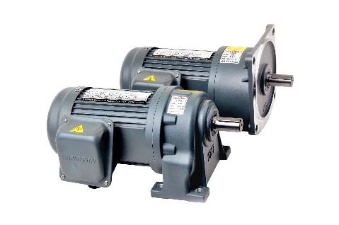
เกียร์มอเตอร์ (Gear Motor) |
|
|
 |
| เกียร์มอเตอร์ยี่ห้ออื่น ๆ |
 |
 |
 |
 |
|
 |
 |
 |
|
-
WANSHSIN
INSTRUCTIONS FOR GEAR REDUCER MOTOR
Welcome to choose WANSHSIN series gear reducer motors (reducers).Please refer to these instructions before installation and using.
1 Before using
1. Please check if the product type, motor power, motor rated voltage, installation, reduction ratio and size of output bearing meet your requirements; if not, please contact your dealer for timely processing.
2. FOR the gear reducer motors (reducers) with plastic plugs in the gearboxes, pull out the yellow small plastic plugs, or else the oil may spill after long hours of running.
2 Environment of use
1. Do not use the gear reducer motor in the environment with explosives, flammable gas, corrosion, or water leaks.
2. Do not forcibly bend, pull or pinch the power supply, cables and motor wires.
3. When the motor is installed, it must be grounded properly with a ground wire, which is located on the junction box.
4. Installation, connection and inspection must be carried out by professional technicians.
5. The installation environment must be dry and well ventilated, the ambient temperature should be -5℃~40℃, and extreme temperatures shall be noted.
6. The gear reducer motor should be installed on a flat and solid base.
3 Installation
1. When the output bearing is connected with the coupler bearing is connected with the coupler, it must be fixed and the two shafts must be parallel, the base should be installed with the bolts of appropriate aperture, and ensure that gear reducer motor is fixed tightly and securely.
2. All the equipment installed on the output bearing must be installed lightly; do not knock the output bearing with a hammer or other blunt objects to prevent bearing damage caused by tight installation.
3. The pulleys, sprockets and gears should be installed as close as possible to the output bearing to reduce bending stress. Connect to the output bearing through sprocket or belt pulley with a diameter no more than 6 times of the output bearing. Please use in combination with H7 tolerance to avoid noise and damage to the bearing surface.
4. After installation, coated suitable anti-rust oil or paint on the surface of the output bearing to avoid rusting.
5. Select appropriate wiring method according to the power supply voltage and connect the wires in the junction box. Wiring error will cause motor burn. According to the rated current on the nameplate, it is recommended to select the appropriate size of power cable according to 5A/mm2 current density to supply power to the motor.
6. When the gear reducer motor with brake function is powered by frequency converter, the brake line (yellow) should be provided with AC 220V power supply separately, and the power supply should be synchronized with the gear reducer motor.
7. The gearbox of the gear reducer motor has been filled with appropriate lubricating oil, and it isn't required to add lubricating before use. After normal use for 10,000 hours, add 0# lubricating oil.
8. After installation, check again if the mounting surface of gear reducer motor is flat, and ensure that no objects prop the motor, or else it will cause motor burn.
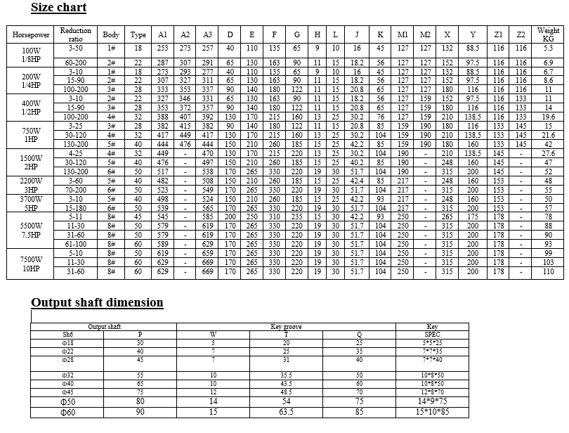
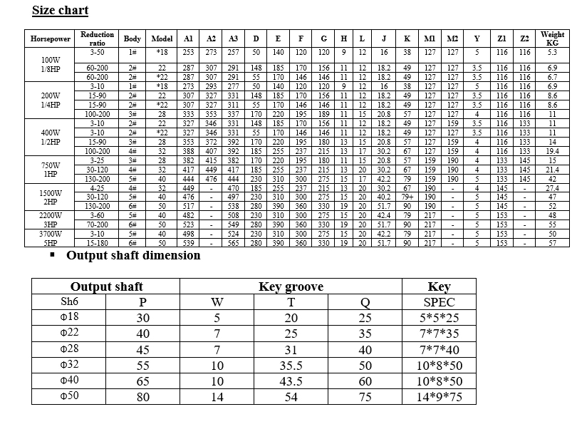
WANSHSIN GH Horizontal three-phase, single-phase aluminum case(brake) gear reduction motor
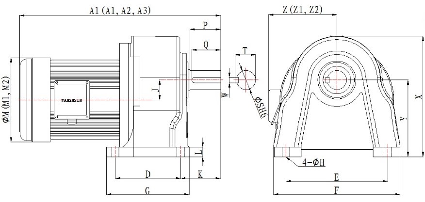
- A1, M1, Z1 are three-phase motor size
- A2, M2, Z2 are single-phase motor size
- A3 is three-phase with brake motor size
WANSHSIN GV vertical with three-phase/single-phase aluminum case (brake) gear reducer
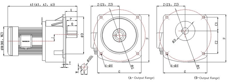
- 1, M1, Z1 are three-phase motor dimensions
- A2, M2, Z2 are single-phase motor dimensions
- A3 is three-phase with brake motor dimension
- * is B type output flange
Remark: 1. 1# body (type is 18) C1 is 33.5, C2 is 65.5
2. 2# body (type is 22) C1 is 40, C2 is 80
Back to menu...
|
|